
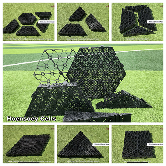
A shallow drainage layout around irregular geometry needs a clear plan for boundaries, penetrations, edges and changes in direction. The aim is not to promote unusual finished shapes. Instead, coordinated parts help the project team create a practical assembly with fewer site cuts and clearer installation planning.
HOENSOEY developed the Cells component family for shallow drainage and water-management applications. This article explains how the parts work together. After the first layout example, use the HOENSOEY Cells layout and specification page for current data and system enquiries.
In this guide
Shallow Drainage Layout Around Irregular Geometry: Common Constraints
Sites rarely provide a completely open installation area. Utilities, foundations, edges, inspection points and landscape features can all affect the layout. Therefore, a single component size may create avoidable cutting or unused gaps.
A coordinated component family gives designers more options. At the same time, the final arrangement should remain simple enough to manufacture, deliver, set out and inspect.
The Five Coordinated Components
H5082 Main Module
The H5082 is the primary structural component. It provides repeatable coverage and forms the core of many modular drainage configurations.
H2582 Horizontal Module
The H2582 supports horizontal infill and edge completion. It can help the assembly follow a planned width without routine cutting.
H1582 Vertical Module
The H1582 supports vertical infill and smaller dimensional adjustments. Multiple units can work with the main modules to complete a regular finished footprint.
H1382 Turning Module
The H1382 helps the system respond to direction changes, curves or local constraints. Nevertheless, every non-standard layout should be shown on an approved installation drawing.
HexConnect Upper and Lower Join Caps
The join caps secure the intended vertical connection and help maintain alignment between layers. Their role is connection and stability, not a customer-facing product shape.
Rectangular Assembled Formats
The individual parts use engineered internal geometry. However, the supplied or assembled system can follow a familiar rectangular project layout. This makes it easier to coordinate dimensions, packaging and on-site placement.
For standard projects, pre-assembled formats can reduce work on site. For constrained areas, the same family can support carefully planned variations. In both cases, the drawing should identify component quantities, connection points, orientation and layer sequence.
Edges and Penetrations
These configuration options can support roads, courtyards, landscaped areas, tree zones, sports surfaces and other shallow drainage applications. For example, a regular paved area may use a repeatable rectangular assembly. A landscape edge may need smaller infill components. A constrained site may need a controlled change in direction.
Still, layout flexibility does not replace project engineering. The designer must confirm hydraulic capacity, structural loads, cover, bedding, wrapping, ground conditions and maintenance access.
Quantity Take-Off
- Define the required finished length, width and height.
- Mark utilities, foundations, edges and access zones.
- Confirm the design water volume and flow route.
- Check the surface load and proposed cover build-up.
- List every component and connector on the installation drawing.
- Confirm which sections arrive factory-assembled and which approved connection steps remain on site.
What the Supplier Needs from Drawings
- Dimensioned plan area, finished level and available construction depth.
- Utilities, foundations, penetrations, boundaries and inspection access.
- Surface use, cover build-up, traffic class and ground-support assumptions.
- Required water volume, flow direction, inlet, outlet and overflow locations.
- Wrapping approach, delivery access and factory-assembly constraints.
A shallow drainage layout around irregular geometry turns a set of coordinated components into a clear project solution. It allows flexibility inside the system while presenting customers with a familiar, buildable finished format.
Send HOENSOEY the site dimensions, loading conditions and drainage objective for a component and layout review.
